This product is not available for new orders. We recommend ordering: CH150.

| Services Available | |
|---|---|
| Repair | No |
| Calibration | No |
| Free Support | No |
Overview
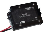
The CH100 is a charging regulator for 12-V rechargeable batteries. This regulator provides built-in temperature compensation to optimize battery performance. It is commonly used when a rechargeable battery is required for the application and the PS150 or PS12LA power supply (7 Ahr) does not contain enough reserve amp-hours for the power supply budget.
Read MoreImages


3D/CAD Files:
Detailed Description
The CH100 regulator connects the BP12, BP24, or other sealed rechargeable battery to an external charging source (e.g., solar panel, wall charger). The circuitry of the CH100 is similar to the PS100, but the CH100 does not include a rechargeable battery. The rechargeable battery must be capable of accepting recharge from a trickle-charge source.
The CH100 controls the current flowing to the battery and prevents the battery current from flowing to the charging source.
Similar Products
Compatibility
Please note: The following shows notable compatibility information. It is not a comprehensive list of all compatible products.
Additional Compatibility Information
Batteries
The CH100 is typically used with the BP12 and BP24 battery packs.
Specifications
| input Voltage (CHG Terminals) | 15 to 28 Vdc or 18 Vac RMS |
| Charging Output Voltage | Temperature-compensated float charge (for 12 Vdc battery) |
| Charging Current Limit | 1.2 A (typical) |
| Power Out (+12 Terminals) Voltage | Unregulated 12 Vdc from battery |
| Length of Red and Black Wires | ~30 cm (12 in.) |
| Dimensions | 10.2 x 7.0 x 3.9 cm (4.0 x 2.8 x 1.5 in.) |
| Weight | 158 g (5.5 oz) |
Quiescent Current |
|
| Charge Source Present | 3 to 5 mA |
| No Charge Source Present | 0 mA |
Related Documents
Product Brochures
Technical Papers
Articles and Press Releases
Newsletter Articles
FAQs for
Number of FAQs related to CH100: 15
Expand AllCollapse All
-
The CH100 has a built-in diode that only allows battery current to flow out of the battery to the 12 V and G terminals. But, because both loads are hooked up to the same battery, the system still drains the same. If there are two loads, and one is of a lesser priority than the other, the lower priority load can be controlled by connecting it to the SW12 on the data logger and turning it off if the battery voltage starts to get too low.
-
No. The CH100 is designed to charge a 12 Vdc battery pack, not a 24 Vdc battery pack.
-
Not quite. The PS24 consists of a 24 Ah battery, a CH100 regulator, and a 10 by 12 in. environmental enclosure. Aside from the enclosure, the PS24 is very similar to a BP24 combined with a CH100.
-
When the current from a solar panel is pushed through long, small-diameter cables, there is a voltage drop generated across the copper cables. This can be minimized by using shorter cables, if possible, or by using cable with a larger diameter (large-gauge wire). Some customers have successfully installed panels up to 50 and 100 ft away.
-
Actually, the current flows up to the maximum amount of amperage based on whether the battery will take the charge or not. The internal resistance of a lead-acid battery increases as it reaches a full charge. The charger/regulator must perform two operations when charging a battery:
- Give the battery all the current it will take when it is in a discharged state.
- Limit the voltage across the battery to a set value based on temperature when the battery reaches a full charge so as not to overcharge the battery.
The voltage rises as the voltage in the battery rises. When the battery voltage rises up close to the voltage limit of the charger, the voltage of the regulator is limited. This causes the battery to take less and less charge (less amperage) because the voltage of the battery and the regulator get to be so close that no more current can be forced into the battery.
-
The red LED light on the CH100 or PS100 comes on whenever there is a working charging source connected. For example, if a solar panel is connected to the device, and the sun is shining, the LED light will turn on until the sun starts to go down. The red LED light should always be on when the device is connected to the wall transformer (when the ac power is present). Thus, the LED light is only a confirmation of power available to charge the battery.
If it is desirable to have an indication that the power switch is on, an LED light can be added to an unused control port on the data logger and a program can be written to cause the LED light to blink every few seconds. Blinking the LED light once every few seconds will not put a large load on the battery, whereas a continuously lit LED draws down the battery more quickly.
-
The PS100 (and CH100) are limited to 1.2 A of input. Because the SP20 20 W solar panel generates 1.17 A, that single panel represents a practical limitation to the input. For panels that generate current greater than 1.2 A, consider the PS200, Smart Power Supply and Charge Controller, or CH200, Smart 12 V Charging Regulator, for up to 3 A of input, or pn 18529, 10 A, 12 V, Morningstar Regulator, which is capable of accepting 10 A of input.
Generally, it is not recommended to connect more than one panel at a time. Differential shading can cause issues, such as the shaded panel acting as a current sink.
-
With a solar panel connected, the quiescent current should be less than a 3 mA draw on the solar panel to light up the LED. (It does not consume current from the battery.) At night, the blocking diode blocks all measurable current from the battery. For power budget calculations, use 0 mA for the CH100 or PS100.
-
A better alternative is to purchase pn 17200, Battery Power Cable, 7 inches, or pn 22024, Battery Cable. Both cables include the plug that connects to the following regulators: CH100, CH200, PS100, and PS200. Using one of these cables ensures that the battery voltage is correct. This is because of the voltage drop across a diode that is between the battery terminals and the 12 V load terminals.
-
The CH100 Charge Controller is designed to work with maintenance-free deep-cycle lead-acid batteries. The voltage of the charger is slightly different than what is required to charge the marine-type flooded-cell battery. Therefore, Campbell Scientific recommends purchasing a deep-cycle battery, such as the BP12 or BP24, rather than a flooded-cell battery. Note that our regulated solar panels, such as the SP20R and SP10R, are intended to be used with, and connected directly to, a user-supplied flooded battery.

