This product is not available for new orders.
| Services Available | |
|---|---|
| Repair | No |
| Calibration | No |
| Free Support | Yes |
Overview
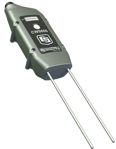
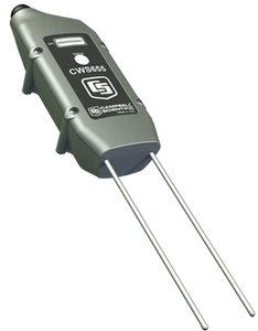
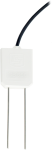
The CWS655 is a wireless version of our CS655 soil water reflectometer. It has 12 cm rods and monitors soil volumetric water content, bulk electrical conductivity, and temperature. This reflectometer has an internal 900 MHz spread-spectrum radio that transmits data to a CWB100 Wireless Base Station or to another wireless sensor. The internal radio's frequency is commonly used in the US and Canada.
Read MoreBenefits and Features
- Versatile sensor—measures dielectric permittivity, bulk electrical conductivity (EC), and soil temperature
- Measurement corrected for effects of soil texture and electrical conductivity
- Internal frequency-hopping, spread-spectrum radio provides longer range and less interference
- Battery powered
- A reliable, low-maintenance, low-power method for making measurements in applications where cabled sensors are impractical or otherwise undesirable
- Transmissions can be routed through up to three other wireless sensors
- Compatible with CR800, CR850, CR1000, and CR3000 dataloggers
Images
Detailed Description
The CWS655 has 12-cm rods that insert into the soil. It measures propagation time, signal attenuation, and temperature. Dielectric permittivity, volumetric water content, and bulk electrical conductivity are then derived from these raw values.
Measured signal attenuation is used to correct for the loss effect on reflection detection and thus propagation time measurement. This allows accurate water content measurements in soils with bulk ≤3.7 dS m-1 without performing a soil-specific calibration.
Soil bulk electrical conductivity is also derived from the attenuation measurement. A thermistor in thermal contact with a probe rod near the epoxy surface measures temperature. Horizontal installation of the sensor provides accurate soil temperature measurement at the same depth as the water content measurement. For other orientations, the temperature measurement will be that of the region near the rod entrance into the epoxy body.
Why Wireless?
There are situations when it is desirable to make measurements in locations where the use of cabled sensors is problematic. Protecting cables by running them through conduit or burying them in trenches is time consuming, labor intensive, and sometimes not possible. Local fire codes may preclude the use of certain types of sensor cabling inside of buildings. In some applications measurements need to be made at distances where long cables decrease the quality of the measurement or are too expensive. There are also times when it is important to increase the number of measurements being made but the data logger does not have enough available channels left for attaching additional sensor cables.
Similar Products
Compatibility
Please note: The following shows notable compatibility information. It is not a comprehensive list of all compatible products.
Specifications
| Measurements Made | Soil electrical conductivity (EC), relative dielectric permittivity, volumetric water content, soil temperature |
| Water Content Accuracy | ±3% VWC typical in mineral soils, where solution EC ±10 dS/m |
| Required Equipment | CWB100 |
| Rods | Not replaceable |
| Sensors | Not interchangeable |
| Weather Resistance | IP67 rating for sensor and battery pack (Battery pack must be properly installed. Each sensor is leak tested.) |
| Operating Temperature Range | -25° to +50°C |
| Operating Relative Humidity Range | 0 to 100% |
| Power Source | 2 AA batteries with a battery life of 1 year assuming sensor samples taken every 10 minutes. (Optional solar charging available.) |
| Average Current Drain | 300 μA (with 15-minute polling) |
| Rod Diameter | 3.2 mm (0.13 in.) |
| Rod Length | 12 cm (4.7 in.) |
| Dimensions | 14.5 x 6 x 4.5 cm (5.7 x 2.4 x 1.77 in.) |
| Weight | 216 g (7.6 oz) |
Measurement Accuracies |
|
| Volumetric Water Content | ±3% VWC typical in mineral soils that have solution electrical conductivity ≤ 10 dS/m. Uses Topps Equation (m3/m3). |
| Relative Dielectric Permittivity |
|
| Bulk Electrical Conductivity | ±(5% of reading + 0.05 dS/m) |
| Soil Temperature | ±0.5°C |
Internal 25 mW FHSS Radio |
|
| Frequency | 902 to 918 MHz |
| Where Used | US and Canada |
| FHSS Channel | 50 |
| Transmitter Power Output | 25 mW (+14 dBm) |
| Receiver Sensitivity | -110 dBm (0.1% frame error rate) |
| Standby Typical Current Drain | 3 μA |
| Receive Typical Current Drain | 18 mA (full run) |
| Transmit Typical Current Drain | 45 mA |
| Average Operating Current | 15 μA (with 1-second access time) |
| Quality of Service Management | RSSI |
| Additional Features | GFSK modulation, data interleaving, forward error correction, data scrambling, RSSI reporting |
Related Documents
Product Brochures
Miscellaneous
Downloads
Wireless Sensor Planner v.1.7 (30.5 MB) 08-08-2013
The Wireless Sensor Planner is a tool for use with Campbell Scientific wireless sensors. It assists in designing and configuring wireless sensor networks.
Articles and Press Releases
Newsletter Articles
FAQs for
Number of FAQs related to CWS655: 33
Expand AllCollapse All
-
Only the rods of the CWS655 should be buried. The body of the CWS655 was not designed for burial, and Campbell Scientific does not recommend burying it for the following reasons:
- While the body of the CWS655 is underground, the radio signal is diminished, and the soil must be disturbed to replace the batteries.
- Eventually, corrosion of the pins occurs where the battery pack connects. Sometimes moisture gets into the sensor electronics and causes irreparable damage.
If a wireless option is desired for fully buried water content sensors, consider using a CR200X-series datalogger with CS650-L or CS655-L cabled sensors.
-
The bulk electrical conductivity (EC) measurement is made along the sensor rods, and it is an average reading of EC over the top 12 cm of soil.
-
Period average and electrical conductivity readings were taken with several CWS655 probes in solutions of varying permittivity and varying electrical conductivity at constant temperature. Coefficients were determined for a best fit of the data. The equation is of the form
Ka(σ,τ) = C0*σ3*τ2 + C1*σ2*τ2 + C2*σ*τ2 + C3*τ2 + C4*σ3*τ + C5*σ2*τ + C6*σ*τ + C7*τ + C8*σ3 + C9*σ2 + C10*σ + C11
where Ka is apparent dielectric permittivity, σ is bulk electrical conductivity (dS/m), τ is period average (μS), and C1 to C11 are constants.
-
The equation used to determine volumetric water content in the firmware for the CWS655 is the Topp et al. (1980) equation, which works for a wide range of mineral soils but not necessarily for artificial soils that typically have high organic matter content and high clay content. In this type of soil, the standard equations in the firmware will overestimate water content.
When using a CWS655 in artificial soil, it is best to perform a soil-specific calibration. For details on performing a soil-specific calibration, refer to “The Water Content Reflectometer Method for Measuring Volumetric Water Content” section in the CS650/CS655 manual. A linear or quadratic equation that relates period average to volumetric water content will work well.
-
No. It is not possible to disable the logical tests in the firmware. If soil conditions cause frequent NAN values, it may be possible to perform a soil-specific calibration that will provide good results.
If permittivity is reported but the volumetric water content value is NAN, Campbell Scientific recommends a soil-specific calibration that converts permittivity to water content. This will take advantage of the bulk electrical conductivity correction that occurs in the firmware.
If both permittivity and volumetric water content have NAN values, it may be possible to perform a calibration that converts period average directly to volumetric water content.
For details on performing a soil-specific calibration, refer to “The Water Content Reflectometer Method for Measuring Volumetric Water Content” section in the CS650/CS655 manual. After a soil-specific equation is determined, it may be programmed into the data logger program or used in a spreadsheet to calculate the soil water content.
-
The dielectric of water at room temperature is close to 80. The firmware for the CWS655 is programmed to change volumetric water content to NAN when the permittivity measurements are greater than 42. When testing in water, look at the permittivity reading rather than the water content reading. If a test is being done for functionality, pull the CWS655 rods about halfway out of the water to see both permittivity and volumetric water content readings.
Note: The CWS655 was not designed for complete submersion in water. To conduct a water test, fully immerse the sensor rods in the water, but do not let the battery pack go under water.
-
The volumetric water content reading is the average water content over the length of the sensor’s rods.
-
Yes, but the pots would have to be large. The CWS655 can detect water as far away as 10 cm (4 in.) from the rods. If the pot has a diameter smaller than 20 cm (8 in.), the CS655 could potentially detect the air around the pot, which would underestimate the water content. In addition, potting soil is typically high in organic matter and clay, causing the probably need for a soil-specific calibration.
-
Campbell Scientific does not recommend using the CWS655 to measure water content in compost. A compost pile is a very hostile environment for making dielectric measurements with soil water content sensors. All of the following combine to make it very difficult to determine a calibration function: high temperature, high and varying electrical conductivity, high organic matter content, heterogeneity of the material in the pile, changing particle size, and changing bulk density. The electrical conductivity values reported by the CWS655 may give some useful information about processes occurring in the compost pile, but it will not be able to give useful readings for water content. In addition, the plastic housing of the CWS655 may likely be damaged by the high temperatures and acids formed during the composting process.
-
The CWS655 works best when the rods are inserted into the soil as parallel to each other as possible. To make parallel pilot holes before installation, use the CS650G Rod Insertion Guide Tool. Minor deflection of a rod during insertion, such as when it contacts a small stone or root, may not affect the readings significantly. Major deflections, however, may cause the CWS655 to operate outside of published accuracy specifications, as well as to damage the sensor housing.