This product is not available for new orders. We recommend ordering: NL241.

| Services Available | |
|---|---|
| Calibration | No |
Overview
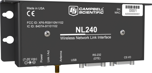
The NL240 is a powerful Wi-Fi network link interface that provides a wireless network connection to data loggers and peripherals. It supports sophisticated networking capabilities, especially when used in PakBus networks with PakBus devices. For example, with the NL240, multiple PakBus clients can be connected to a single data logger at the same time.
Read MoreBenefits and Features
- Low power consumption
- Wi-Fi-to-CS I/O bridging provides direct access to Internet protocol capabilities of CR6, CR800, CR850, CR1000, or CR3000 dataloggers
- Powerful PakBus routing capabilities
- Serial server functionality for networking Campbell Scientific devices, as well as third-party devices
- Provides IP connectivity for communication with LoggerLink smartphone app and LoggerNet PC software
Images


Detailed Description
The NL240 can take advantage of the thousands of Wi-Fi hotspots available in cafés, universities, hotels, and airports. Wi-Fi also provides encryption to protect traffic and uses a global set of standards so the same device can be used internationally.
The NL240 is an industrial device that goes beyond the typical Wi-Fi serial device server. It supports Wi-Fi communication with an iOS or Android device when used with our LoggerLink apps. By providing direct access to all the IP capabilities of the CR800, CR1000, and CR3000 dataloggers, the NL240 provides:
- M2M communication of data and events
- PakBus communication over TCP/IP for remote configuration, control, and data collection
- HTTP and FTP for posting, retrieving, and local hosting of data
- Email client for data and control messaging
- ModBus TCP/IP, DNP3, and NTCIP ESS industrial protocol support
Powering the NL240
The NL240 is typically powered by the data logger through the CS I/O port. When the NL240 is connected to the RS-232 port, a field cable (pn 14291) is used to connect the NL240 to an appropriate 12 Vdc power supply. A wall charger (pn 15966) is used when the NL240 is in an office next to a computer.
Similar Products
Compatibility
Wi-Fi ad hoc networking is provided for the purpose of networking between NL240 interfaces. Ad hoc networking is supported by iOS, allowing an iOS device to connect to an NL240 that has created a network. Wi-Fi ad hoc networking is not supported natively by Android OS and is difficult to support on Windows 7 and greater.
Software
Our Device Configuration Utility must be version 2.03 or higher.
Data Logger Considerations
| Data Logger | Serial Server | PakBus Router | Bridge Mode* |
| CR300♣ |  |
 |
|
| CR200(X) Series |  |
 |
|
| CR800/CR850 |  |
 |
 |
| CR1000 |  |
 |
 |
| CR3000 |  |
 |
 |
| CR5000 |  |
||
| CR9000X |  |
||
| CR6 |  |
 |
 |
| CR1000X |  |
 |
 |
| CR510-PB |  |
 |
|
| CR10X-PB |  |
 |
|
| CR23X-PB |  |
 |
|
| Mixed-Array Data Loggers |
** |
Notes:
♣The CR300 connects to the NL240 using a 10873 serial cable that is not supplied with the CR300 or the NL240. The CR300-series dataloggers are not compatible with the bridge mode functionality in the NL240 interface.
* The data logger OS must be OS 25 or higher for bridge mode applications.
** It is possible to use an NL240 to connect to a mixed-array data logger (e.g., CR10, CR10X, CR23X, 21X, CR7) by using an SC32B between the data logger's CS I/O port and the NL240's RS-232 port.
Specifications
| Compliance | CE compliant |
| Material | Aluminum case with black anodized finish |
| Configuration |
|
| CS I/O Port | SDC 7, 8, 10, or 11 (does not support ME) |
| RS-232 Port | DTE, DB9 Pin (Male) |
| USB Port | Micro-B |
| Operating Temperature Range |
|
| Power Connector | CS I/O Port, DC barrel connector (not powered over USB) |
| Powered Over | CS I/O or barrel plug |
| Supply Voltage | 7 to 20 Vdc |
| Connections/Routes Supported |
|
| Dimensions | 16 x 6.73 x 2.54 cm (6.3 x 2.65 x 1 in.) |
| Weight | 177 g (6.3 oz) |
Communication Rate |
|
| RS-232 Port | 1200 bps to 115.2 kbps |
| CS I/O Port | 9600 bps to 460.8 kbps |
WLAN |
|
| Antenna Connector | RPSMA |
| Technologies Supported | 802.11b/g/n, WPA, WPA2 /TKIP or AES, WEP, WEP(open), APIPA/AutoIP, IPv4, IPv6, ICMP/Ping, ICMPv6/Ping, TCP, DHCP Client, SLAAC, DNS Client, HTTPS Proxy, Telnet Server, TLS, PakBus, Modbus, TCP/IP |
| Topologies | Infrastructure and ad-hoc |
| Transmit Power | 7 to 17 dBm (5 to 50 mW) |
| Rx Sensitivity | -97 dBm (< 8% PER) |
| Frequency | 2.4 to 2.5 GHz (2.4 GHz ISM band) |
Power Consumption |
|
| Maximum | 950 mW |
| Typical (Always On) |
|
| Typical (Low Power Mode Enabled) |
|
| Sleep | 16 mW |
Related Documents
Product Brochures
Technical Papers
Compliance
Downloads
NL240 Drivers () 01-01-2014
Windows USB drivers for the NL240 are installed via the Device Configuration Utililty. In the Device Configuration Utility, click on the link "install the device driver for the NL240" in the main body of text for the NL240.
Note: Drivers must be installed before connecting the NL240 to your computer.
NL240 Firmware v.10.03 (671 KB) 04-09-2018
Current NL240 firmware. Requires the Device Configuration Utility and a USB micro cable.
Note: When updating to OS 10.03 from OS 6 or previous, settings will be reinitialized to factory defaults. When updating to OS 10.03 from OS 7, settings will be retained.
Articles and Press Releases
FAQs for
Number of FAQs related to NL240: 15
Expand AllCollapse All
-
No. Antennas are ordered separately, allowing customers to choose the best antenna for their application and site.
-
No, it is not.
-
Yes. The NL240 wireless network link was designed for this purpose.
-
The NL200-series of devices can be set to bridge the Ethernet or Wi-Fi interface and the CS I/O interface. All packets that come into the device via Ethernet or Wi-Fi will be transferred to the data logger over the CS I/O port. This enables the data logger to make all of its IP-related services available. Configuring an NL200-series device with bridge mode enabled is analogous to adding a native Ethernet or Wi-Fi port to the data logger. Bridge mode does not use PPP.
-
The NL201 and NL240 are available options.
-
Connect one data logger to the RS-232 port (6784) and the other data logger to the CS I/O port (6783). To access a data logger on the RS-232 port, use the IP address xxx.xxx.xxx.xxx:6784. To access a data logger on the CS I/O port, use xxx.xxx.xxx.xxx:6783. For setup instructions and configuration assistance, refer to the NL240 instruction manual, use the LoggerNet Network Planner tool, or contact Campbell Scientific.
-
If the NL240 is on a different network from the server running LoggerNet, either the station or LoggerNet needs to be able to initiate a connection to the other:
- The NL240/data logger needs an IP address that is accessible to the LoggerNet computer
OR
- LoggerNet needs an IP address that is accessible to the NL240/data logger.
-
The NL201 and NL240 are powered via the DC barrel connector and/or the CS I/O port. Sometimes, users who are using the network link
interface as a serial terminal server, PakBus router, or Modbus gateway want to connect their devices via the CS I/O port while
providing power only through the DC barrel connector and a 12 V source (such as a data logger SW12V output). In this scenario, a jumper
inside the NL201 or NL240 can be removed, preventing the interfaces from always being powered by the CS I/O connections. For more
information, refer to the instruction manual for the interface. -
It depends on the application, funds available for new hardware, and the quantity of data that will be collected. Viable options include the NL240, RF4xx spread-spectrum-series radios, RF32x UHF/VHF radios, and cellular modems.

